Autoregulator
A device to automatically regulate and synchronize a pendulum clock.
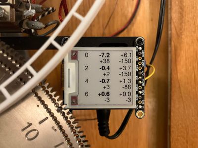
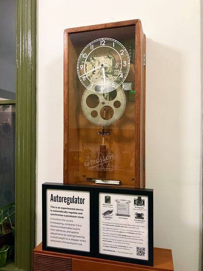
Inspired by the electric synchronization schemes of the past (and by modern solutions like this one), I built a device that uses a small stepper motor on the pendulum rod to raise and lower a small weight, to gently bring a clock to time.
It is driven by an ESP32 microcontroller that uses WiFi to compare the clock’s timekeeping against UTC and write logs to a database, and an e-ink screen to display the state of things. The firmware is available on GitHub.
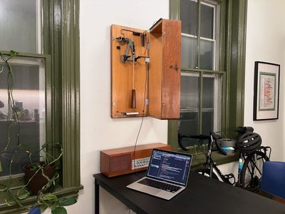
My Ericsson master clock served as the test subject for this project.
Building the first prototype
To validate the concept, I 3D-printed a small bracket with a bolt that raised and lowered a heavy nut, to see how much it affected the rate. It was quite effective indeed.
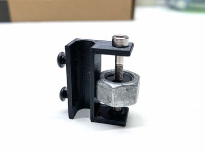
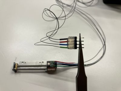
I figured I would design something to mate a stepper motor to the bolt, and then conveniently found the FIT0708, a micro stepper that comes complete with a threaded rod and doesn’t even need a hardware driver; it can be driven directly by a microcontroller. This was such an ideal choice that it really got the project rolling.
The full list of hardware:
- DFRobot FIT0708 stepper motor
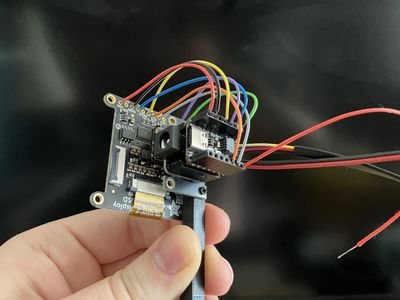
- Adafruit QT Py ESP32-S2 microcontroller
- Adafruit DC Power BFF Add-On, which steps down the clock’s 9VDC to 5VDC. As a bonus, its input is wired to both a barrel jack and terminal connectors, so it neatly adapts the power supply’s barrel connector to the clock’s original wiring.
- Adafruit DS3231 Precision RTC, to provide the reference time. A real-time clock chip with a thermocompensated quartz crystal and its own button cell, so it keeps time while the rest of the electronics are asleep.
- Adafruit ThinkInk E-Ink display, for visibility into what’s going on. E-Ink requires no power to hold an image, which is perfect for something that spends most of its life asleep.
- Adafruit 36AWG wire, more on this later.
The controller
I had prior experience with the Espressif ESP32, particularly Adafruit’s nifty QT Py implementation. The ESP32 can be programmed like an Arduino but has excellent built-in support for WiFi and very low power deep sleep, which is ideal for applications like this one where mains power might not be available.
The ESP32 is woken by a hardware interrupt: a connection between a particular pin and either 5V or ground. If the Autoregulator were added to a conventional clock, this signal could come from something like a magnet on a wheel closing a reed switch – but as the Ericsson has an unused bell program circuit, it seemed sensible to wire the ESP32 directly to that. Very luckily, the tiny QT Py has just enough inputs to support everything: taking the interrupt from the clock, communicating with the RTC, and driving both the stepper and the e-ink display.
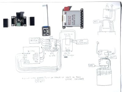
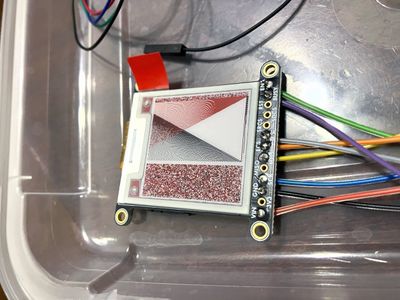
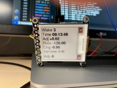
The firmware is written such that, with each “wake,” the ESP32 connects to WiFi and requests the current UTC time from an NTP server (compensating for the duration of the request); applies an adjustment; then updates the e-ink screen with the results and logs them to a database.
When starting from a cold boot, it takes three wakes for the ESP32 to learn what to do:
- On the first wake, it just logs the reference time.
- On the second wake, it logs a new reference time and compares the two, and calculates the clock’s rate. It doesn’t yet know how much a given adjustment will affect that rate, so it makes a test adjustment to find out.
- On the third wake, it knows both the current and previous rate, and can calculate the adjustment factor.
From that point forward, it knows how much of an adjustment to make to get the rate roughly to zero.
Of course, the ESP32 doesn’t really know the full time of day shown on the clock – only the minutes shown when the interrupt is triggered, which, in the Ericsson’s case, is at the top of the hour. The ESP32 assumes the clock is at least correct to within half the duration of the last sleep period – and in this way, it can assume a clock difference to compare to the reference difference, to accommodate for varying triggers. (This also allows it to tolerate missed triggers, as well as discard spurious triggers that are wildly out of time – a real boon when the signal is noisy during prototyping!).
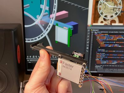
To mount the controller components (display, power board, and ESP32) in the Ericsson clock, I designed a 3D-printed bracket that sandwiches between the movement’s lower right pillar and its own mounting bracket. This way, the display appears just beneath the dial, opposite the old paper condenser on the other side, and near all the original connectors.
The compensator
I knew that connecting the controller to the compensator on the pendulum rod would be the most invasive and fraught aspect of the whole system, since it calls for a wired connection that, ideally, imparts minimal effect to the pendulum's swing. (This could be avoided by designing an Autoregulator fully contained on the pendulum rod, battery and all, but it would need to sense timekeeping from the movement or vibration of the pendulum, which is out of scope for the moment.)
I thought of trying the sort of flex cable used to drive inkjet print heads, but another fortuitous discovery revealed itself: Adafruit’s 36AWG wire. It is so thin and flexible it feels like thread. It has a bit of precedent in the Ericsson too, which uses flexible braided wire to connect its moving switches to fixed terminals.
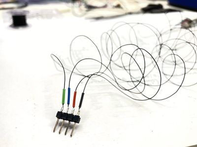
Rather than attempt to solder the 36AWG wire directly to the motor’s tiny daughterboard, I kept a bit of the original wiring and cut and stripped it in a staggered pattern so there wouldn’t be any cross-contact; then soldered the other ends to a pin header to plug into the socket strips on the ESP32. The wires are so small that I was able to thread bits of colored insulation from other wires over them to keep them straight.
For a test run, I attached the FIT0708 motor assembly and wires to the pendulum rod – a wooden dowel – with the simple expedient of gaffer tape.
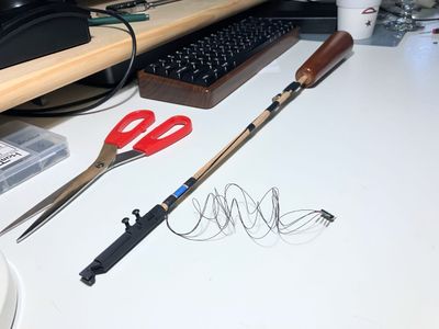
The small nut on the motor’s threaded shaft needed a bit of weight added to be effective at regulating, so I 3D-printed a bracket that holds a pair of bearings, the best combination of small, heavy, and attractive I had on hand.
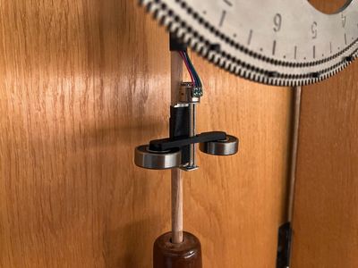
On installation, I looped the wire over the suspension spring mount, near the pivot point of the pendulum, to minimize deformation of the wire and any effect on the pendulum’s motion. Happily, it worked a treat.
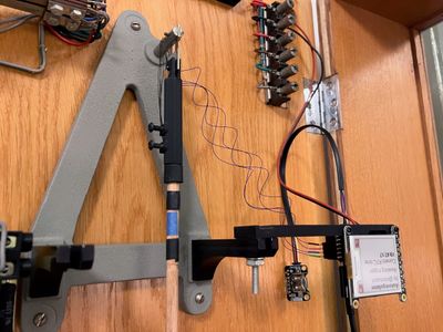
Once the pendulum is coarsely regulated within range, the Autoregulator does the rest!
Synchronization and refinements
After a year of testing autoregulation with great success, I sat down to have a go at adding synchronization functionality.
This would be tricky, since it calls for two adjustments to be applied that might compound or counteract each other: one to apply a regulation, and one to temporarily offset the regulation to make the clock time drift toward the reference time. That adjustment is reversed at the next wake.
It also called for a better handling of “stall” conditions, where the motor reaches one end of its run and can't move any further. The ESP32 detects this by sensing a rate change that's less than expected, and displays an error asking the clock owner to apply a coarse adjustment to get the rate within a window the Autoregulator can act on. The synchronization offset complicates this, since it might apply an adjustment that falls outside this window. At this writing, the solution I chose was to apply a reasonably small offset, no matter how out of sync the clock is, so it drifts slowly toward the correct time. This way, it’s unlikely to stall as long as the coarse regulation is close enough.
A revelation about how pendulums work
As part of this update, I wanted to refine the physical implementation of the prototype: to paint the pendulum rod, 3D-print more permanent brackets to hold the compensator and wires in place, and program the Autoregulator to display data more compactly so the last four “wakes” can be compared.
I also thought I'd try moving the compensator further up the rod, toward the middle, so it is still visible behind the program dial but not visually clashing with the wooden bob.
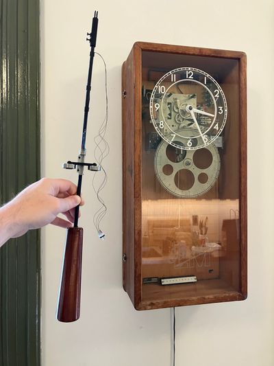
To my surprise, after reinstallation, the Autoregulator complained that regulation was not effective at all. At first I thought it was a wiring problem, so I rebuilt the connector with glue for stress relief (which was needed anyway) – but that wasn't it.
I had assumed that placing the Autoregulator in the middle of the rod might be less effective, but still somewhat effective, as I knew that fine regulators and tower clocks often have a little tray near the center to hold small weights for this purpose (e.g. Big Ben’s penny coins, and this automated example at CERN).
A bit of research revealed my folly. I was conflating amount of mass with the position of that mass, and adjustments to these values have opposite effects at the same points along the pendulum: amount matters near the center (hence the trays), whereas position matters near the ends. What's more, positional adjustments near the top have the inverse effect of adjustments near the bottom: lowering the mass does more to raise the pendulum’s center of rotation, causing it to go faster.
This was hard to believe intuitively, so I had to try it.
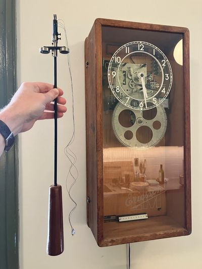
I programmed the Autoregulator to be aware that its test regulation could have a positive or negative effect, and to make future regulations accordingly. The test would be most effective with the compensator as close to the top of the rod as possible. Incredibly, it fit so perfectly, with just a few millimeters’ clearance above the crutch and in front of the mounting frame, that it would be natural to leave it there – if it worked.
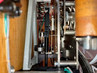
Sure enough, it does!
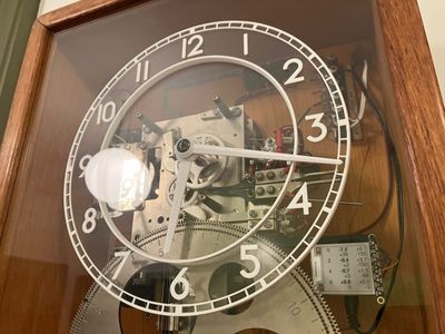
The Ericsson clock, governed by its fully-fleshed-out Autoregulator, now drives a secondary clock with plans to add more – bolstered by the confidence that the system will remain both accurate and synchronized.