Entropon Decelerator
An Arduino project to simulate time slowing.
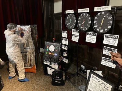
The Entropon Decelerator is my contribution to Entroponics, a performance art piece put on with friends for the Holistic Quantum Activation Art Expo held annually in Philadelphia. Entroponics promises the health benefits of a localized slowdown of time inside a tiny chamber – never mind that the process takes longer than the time saved.
Building the Mk II

The ENTROPONICS™ Entropon Decelerator Mk II is the culmination of several days of effort.
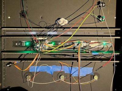
The decelerator is comprised of a rackmount control unit, and a chamber unit inside the deceleration chamber. At the heart of each lies an Arduino Nano 33 IoT, linked to the other via a serial connection. The Arduino code can be found here.
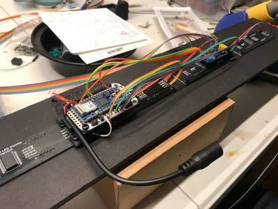
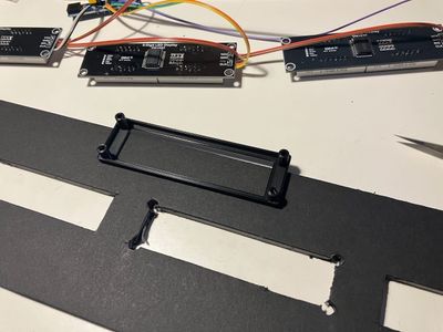
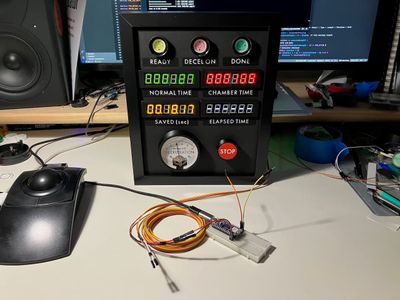
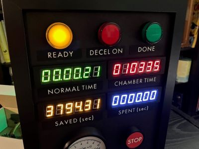
During a deceleration session, the time of day inside the chamber gradually slows. The current normal time, chamber time, difference (“time saved”), and elapsed time (“time spent”) are shown – in green, red, yellow, and white, respectively – on digital displays driven by TM1637 controllers. The Arduino lives on a proto board directly behind these displays, as each one greedily demands a dedicated pair of pins (unlike the more reasonable components in this project that implement the I2C protocol so they can all share the same two pins).


Special recognition goes to a third Nano 33 IoT which powered the Mk I Entropon Decelerator and was to be reused for the Mk II, but was deprived of this honor when a corrupted bootloader bricked it. Its honorable sacrifice provided the “opportunity” to rebuild the proto boards more sensibly with header pins instead of hardwiring. A fourth Nano was used to conduct careful unit testing after this incident.

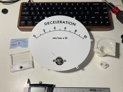
The session state is displayed via indicator lights, and deceleration rate via a voltmeter driven with pulse-width modulation. The control unit manages this state and controls the timing, in constant consultation with a DS3231 real-time clock, and communicates this to the chamber unit via serial. (This is the main improvement of the Mk II over the Mk I, which used only the one Arduino and drove the chamber unit via a very long unshielded I2C connection, with predictably poor results.)
The control unit has buttons to start and stop the session, and knobs to control the maximum deceleration, rate of change (“power”), and rate of recovery. In the code, the buttons are handled with interrupts rather than polling, as the loop code runs a little too slowly for polling to be reliable.
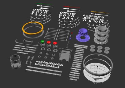
All the controls and displays are, in part, 3D-printed on a Prusa MK4 with MMU3.



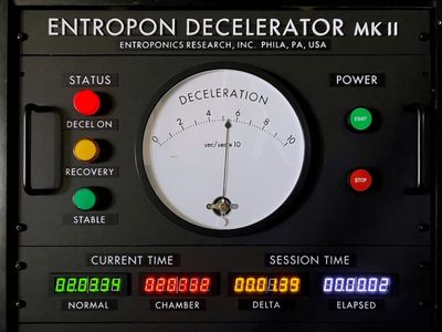

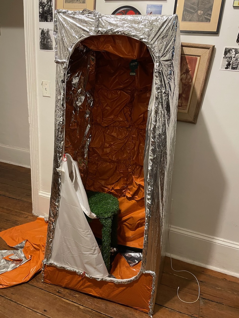
The chamber unit duplicates the digital displays, status lights, and deceleration meter from the control unit, but offers only a stop button, which is communicated back to the control unit via serial.

The control unit also drives a set of large analog clocks: two that duplicate the digital displays for normal time and chamber time, and one to accumulate the total count of seconds saved over the demonstration. Each clock uses its original mechanism with a Lavet-type stepper motor, driven by L293D H-bridge motor controllers via a PCF8574 pin expander. (As the timing of these pulses is crucial, this is the one place the loop code is allowed to use delays, hence its slowness.) A spare output from one of the L293D controllers is used to power a rotating strobe light during deceleration. Another L293D in the chamber module, wired in parallel with the voltmeter, drives a small vibration motor attached to the helmet in the chamber, to achieve maximum discomfort for the wearer.


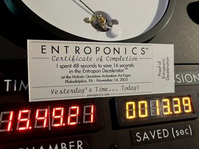
Finally, the control unit connects to a private WiFi network running off an old router, which in turn connects via Ethernet to a BOCA Lemur thermal ticket printer. When a deceleration session concludes, it sends the printer the raw FGL commands to print a certificate logging the time spent and time saved — the latter, of course, always being less than the former, as these things tend to go.