Ericsson Master Clock
Mechanical and electrical restoration of a 1950s Swiss-movement master clock, plus a new dial and pendulum.
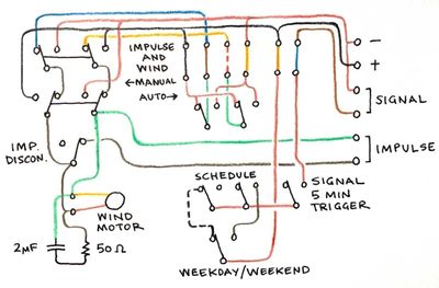
This master clock by L.M. Ericsson (yes, that Ericsson!) uses a Swiss Moser-Baer movement, with connections for a bipolar secondary clock circuit and a bell circuit, which can be programmed up to every five minutes with separate programs for weekdays and weekends.
See also my Autoregulator project, for which this clock served as an intrepid test subject.
Restoration and a new dial
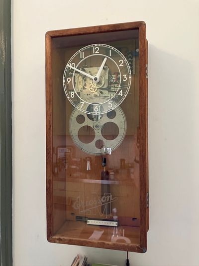
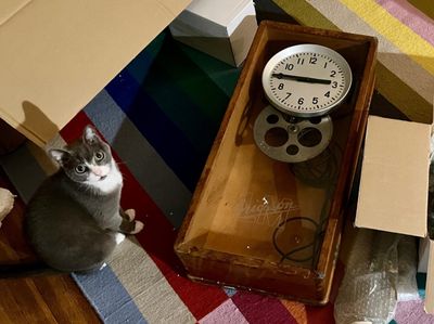
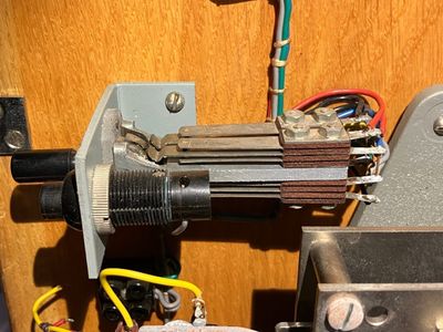
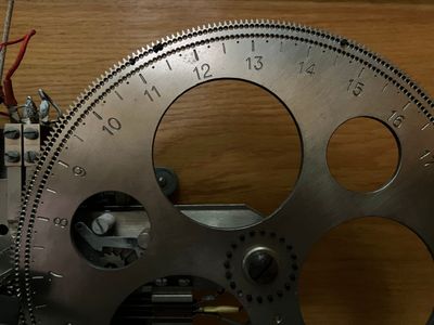
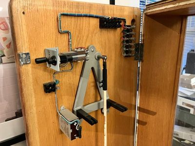
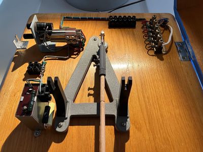
The clock arrived from eBay Germany from a collector’s estate. Though it was missing the pendulum and has quite a few signs of wear, I was drawn to it instantly for its clever mechanism, carefully-arranged wiring, shadow-box-like case, and the lovely etched glass. The original dial is also great in a utilitarian sort of way, but from the beginning I had no intention of using it, since it hides all the best bits.
New pendulum
I decided to fabricate a new pendulum first, to seek signs of life. The suspension spring was bent but present; enough to get on with. I used a 1/4” dowel for the rod, an upside-down furniture leg for the bob, and a 3D-printed hook. The clock accepted it eagerly and, even without a service, began ticking away happily.
Disassembly and service
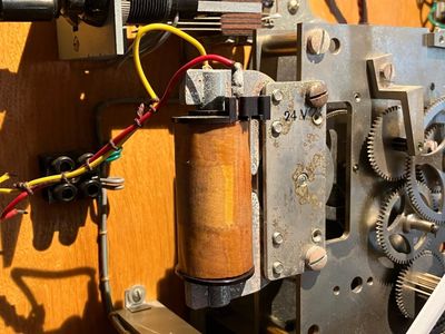
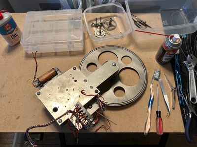
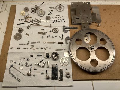
Disassembly demanded a fair bit of patience and penetrating oil, as most of the fasteners had oxidized in place.
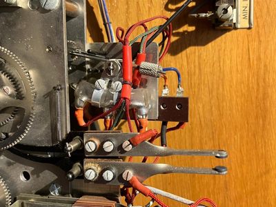
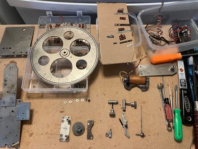
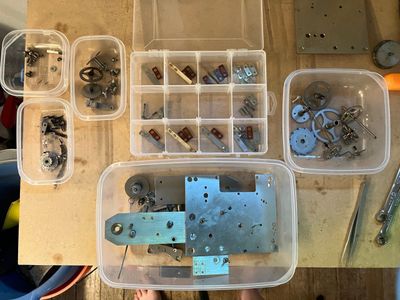
It demanded careful organization, too – especially for the switches, which are composed of several layers of contacts and insulators and must be reassembled in exactly the right order.
Electrical safety
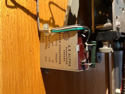
In the meantime, I sought the advice of experts on the NAWCC forums on how to handle the electricals (as well as whether there might be asbestos present – which there isn’t). Of particular concern is the resistor-capacitor pair, used to help suppress flyback arcing. One gentleman kindly advised me the paper capacitor was probably bad. Since I have an LCR meter, I was able to indulge his interest – and we determined that, indeed, it was liable to go explody if powered up.
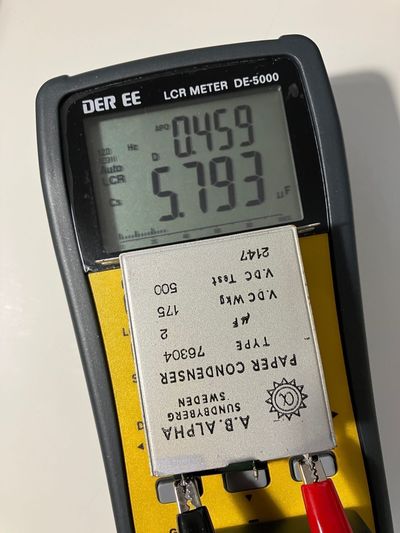
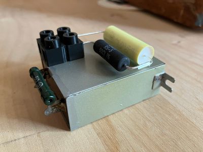
Fortunately it’s inert if left unpowered – so I decided to leave it (and its matching 50Ω wire-wound resistor) in place for originality, and attach modern components to the side. I couldn’t find a black Euro-style terminal block to match the clock’s existing ones, so I bought a white one and transplanted its hardware into a 3D-printed black one.
New dial
To showcase the clock’s mechanism, I decided to fabricate a transparent skeleton dial – and rather than copy the original dial exactly, I decided to imitate the pilot dial from a matching Ericsson punch clock from the same period – no less utilitarian, but with a bit more visual interest (and there is precedent for a similar design in other Ericsson master clocks).

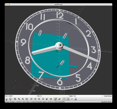
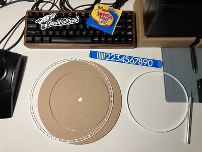
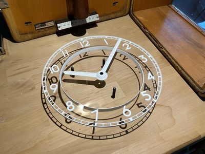
I settled on a design made of two pieces of acrylic and 3D-printed legends, standoffs, and hands, assembled with superglue and M3 screws. The double-level design adds more visual interest and improves readability since it brings the tick marks closer to the minute hand. The acrylic was cut by SendCutSend (who included – fittingly enough – Swedish Fish).
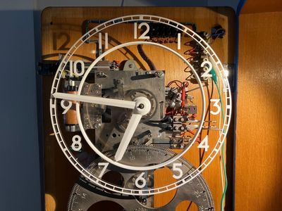
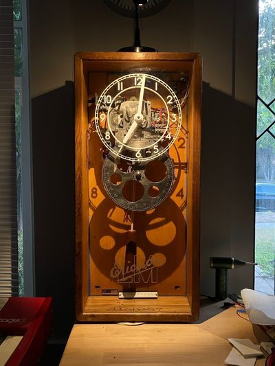
All in all, a fortuitous piece for my first vintage master clock. It will appear again on this site, since I plan to use it as a test bed for some other development projects.